Click on a photo to show a larger copy in a separate window.
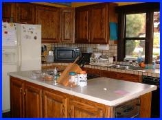
The old kitchen. In this 10x12 space, there's only 32" of space between the front of the range (partially hidden by the knife block) and the edge of the sink counter. The compactor is in the island, not visible here, facing the dishwasher door at the right. You can't open both the compactor and the dishwasher at the same time.
The cabinets shown in the island are only 3" deep inside – to allow room for range and compactor – only good for spices, bottles, and some narrow things. To the right of the range there are four full-depth drawers. Not much storage under the island. We had replaced the butcher-block island countertop with Wilsonart SSV solid-surface material.
There is about 28" of space between the fridge and the island; this was 5" worse before we installed the counter-depth refrigerator.
In the right foreground, outside the photo, is the eating area. The traffic pattern is abysmal: microwave, toaster-oven, and coffee jammed in a corner. Dishes and glassware in the wall cabinets over the toaster-oven. Fridge far from the table. Everyone walks around the counter on both sides to get anywhere! The dishwasher blocks most of the space between island and sink counters.
There is another 16"-deep countertop to the left, outside the photo, dividing kitchen and living room. There are five base cabinets and drawers here, which helps tremendously with storage.
This room was gutted and turned into a TV/stereo area, since it's open to the living room.
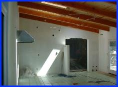
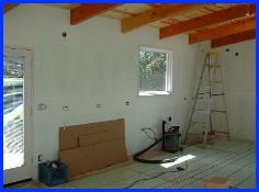
The New Kitchen (above) is an added room, extending the house west beyond the old eating area. The room is 17x28, about 475sqft.
Looking east. This photo is taken from the NW corner, in the dining area. The archway looks into the old kitchen. The archway is in a double-thick wall: we cut out the bay window and framed a full four walls for the new room, then joined it to the existing exterior wall. Thus there was no need to bring the old room up to current California earthquake codes.
The short wall in the center is about 60" tall; its purpose is mainly to hide the cooking area from guests as they enter through the archway. They'll see the view first, then can turn and see the business-area of the kitchen. It also provides a convenient place for the heating thermostat, a light switch, and an outlet (not visible here). The two boxes near the top provide power, CAT5, and coax lines for the top of the cabinets in that corner. I don't know what will go atop them, but it's a nice display area, so wiring it made sense. The small white block in the sun is a GFCI outlet that will end up inside a cabinet containing a small microwave for use while I cook. (The other, larger, micro will sit on the countertop along the sink wall.)
The island, about 4x8ft, will go where that block of wood is on the floor; there will be two stools about where the loop is in the extension cord. It'll be 42" from the front of the range at the left. There's a full 36" between the end of the short wall and the edge of the island.
Two 90"-tall pantry cabinets go in the right rear corner. They'll cover the black vent pipes down near the floor. The two boxes near the ceiling in that corner provide power and coax for a small FM radio atop the tall cabinet. French doors open onto the front deck, which continues to the front door on the east side of the old kitchen. This deck opens onto the driveway, for easy access by guests (or when we buy groceries).
Naturally, you can't miss the Techlighting Monorail track lighting, which I installed a few days before shooting the photo (15 Sep 2002). More details follow later in the story.
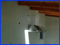
Skylights are 2x4ft; the pair shown can be cranked open. One above the archway (not visible, but that's its shaft of light) and over the main sink are fixed.
The hood is a 54" Vent-A-Hood Emerald model, 600cfm. It's mounted so that it will be about 72-73" above the finished floor, or about 36" above the range.
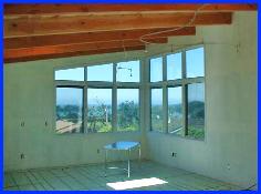
The view, looking west.We overlook a county park and the Pacific Ocean. The photo is taken from about the archway area, looking west. No, that isn't our dining table, but that's where it will go. You can see the screens on the outermost windows; they're casements for the prevailing ocean breeze, which comes right at this corner. The light on the floor is from the skylight over the main sink, to the left outside the frame.
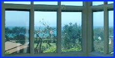
Closeup of view. The visible houses are the only ones that can be built here, so the view is unblockable. The county park is where the flagpole is. Behind the row of cypress trees (seen in the leftmost window) is a coarse sandy beach. It's not a swimming beach, so it has no crowds. Every July 4, the park is packed all day for the town festivities, followed by the fireworks show from the beach behind the park. I thought we had ringside seats before, but the view from this window is even better!
The South Wall. The double main sinks will be centered under the four-foot-wide window where the shop vac sits. The only upper cabinets will go between the window and the west wall (about where the ladder is now.) This entire wall is countertop and base cabinets (actually drawer bases) from the milk crate to the corner at the right.
Looking northeast, from the main sink toward the range. The light areas on the north wall, flanking the range area, are from the skylights above the island (seen in the first photo.)
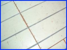
The floor. The room has hydronic radiant heating. The subfloor is built from WarmBoard panels, which are a composition-ply material similar to 1-1/8" plywood. The top (green) surface is a 1/32" layer of aluminum. Grooves every 12 inches hold cross-linked polyethelene (PEX) tubing, which carries hot water to heat the room.
Typical hydronic installations are done by attaching tubing to a plywood subfloor, then pouring a layer of cement or concrete over the tubes. The finished floor is then applied atop the concrete. Other systems install the tubing below the floor, with metal reflector sheets below the tubes to reflect heat upward. The WarmBoard system is more efficient and has quicker response than those traditional systems. The tubes are glued down and the finished floor applied. Tubing can be farther apart than with traditional methods, because the increased efficiency requires lower heat.
The WarmBoard panels come with either a full 8-foot set of parallel grooves, or there are U-turn panels with turns at each foot. Using a router bit supplied by WarmBoard, we routed several custom u-turns into the floor to reverse the tubing direction, so that no tubes run under any cabinetry, appliances, or the island. This serves two purposes: the cabinets are not heated, and the cabinet installers won't damage tubing if they attach to the floor.
One run of tubing ducks beneath the floor at the island, popping back up after it's clear.
Using the WarmBoard panels required me to spend considerable time in the design phase, ensuring that the parallel grooves all missed the cabinetry on the north and south walls. Because the grooves are so far apart, it was important to decide on the distances from those walls before we began laying the subfloor.
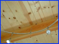
The TechLighting Monorail Lighting. I'll start with the large, more difficult section of Monorail. This section consists of three 8-foot sections. It roughly defines the cooking/island area of the kitchen, using its whimsical curvy shape to contrast with the sharp rectilinear lines of the cabinetry.
I began by laying a 24-foot length of electrical cable (12/3 Romex) on the floor, knowing that would be both flexible and rigid enough to take and hold a shape. Since the outline of the island is drawn on the floor, I'd know how to lay out the track shape.
After I got the shape I wanted, I traced it on the floor with pencil. (This is one advantage of working before the finished floor is in place!) Then I bent the Monorail track, one section at a time, matching it to the line on the floor. I joined the sections and laid the whole assembly on the floor.
Using a plumb bob, I determined the ceiling-hanger positions. The instructions suggest a hanger at every joint (two for me), and every three feet. I used 2.66 feet, so the hangers were evenly spaced across the 8-foot sections. For a 24-foot run, I needed ten hangers. Each hanger comes with 12 feet of plastic-coated stainless cable, so I have lots of hanger cable left over.
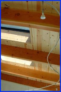
Each hanger is attached to the roof boards with a single drywall screw, with more than enough strength to do the job. These screws also minimize damage to the wood, which made moving the hangers easier (several needed remounting like this).
Hanger detail. The beams are 4x10 douglas fir; the ceiling boards are 2x8 pine tongue & groove. I chose a satin nickel finish for the monorail, to match the stainless appliances and sinks. The monorail's center insulator is white; there are several colors available, including clear.
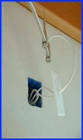
Power is fed to the large monorail sections via a standard 2x4 wall box. The transformers for all three tracks are wall-mounted in the crawlspace below. They're easy to service and invisible. I ran #8 wire to the two large tracks (this one and the one at the sink wall), and #12 to the kitchen table track, which has fewer lamps. (There was no need to go with #8, but we had extra left after wiring the range.)
The track is not yet installed along the sink wall, because it would be vulnerable to attack by the cabinet installers as they hang the upper cabinets and tall corner shelves in the southwest corner. I'll wait till they're done before installing it. After doing the big track, installing a wiggly 16-foot straight run will be easy.
Techlighting makes several types of power feeds, but I like the exposed wiring. And, since they're white, they'll go with the white accents in the kitchen.
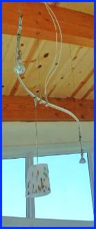
The Table Lamp consists of a four-foot section of track, three hangers, a pendant, and two MR16 heads. I bent a smooth S-curve to roughly follow the 45-degree line of the dining table. It's hung high enough to be out of anyone's line of sight, to avoid competing with the view. If you look above at the two view photos, you'll see that the track and MR16 heads are in the upper-window area, and the pendant aligns with the thick mullion between the uppers and lowers. Thus nothing really stands out. Power is fed through a ceiling box, identical to the wall feeds.
The heads (Techlighting "Cam" 3-inch) were subsequently changed to the more-decorative white glass cones, facing downward. They're MR11 heads, which let let me downsize from the 35w MR16s to the small 20w MR11 lamps; this helped reduce and brightness of the fixture. Because there's a little light from the rear of the lamps, we get a soft glow on the ceiling.
One task left to do was to tack the wires together with hot glue so that they cascade down, curving as a pair to the track.
Overall Techlighing Notes
For simplicity, I installed the identical Techlighting 300w remote magnetic transformer for each track. Though using magnetic instead of solid-state makes dimming hard, I don't plan to dim. A magnetic transformer doesn't care about minimum load the way a solid-state transformer does. The table lamp uses only 120w in its present configuration, so the transformer is loafing. Had that been a 300w solid-state supply, 120w might have been down near the minimum load for the supply.
Using #8 wire was more difficult and cost a few bucks more, but I wanted to minimize voltage drop from the transformer through the 15-20 feet of wire.
The flexible standoffs (the cable hangers) are neat. The part at the track end has a friction clamp for the hanging cable: you simply pull on the cable and slide the track upward. To release the cable, you press down on the ring where the cable exits at the top. Super. When you've got it right, you clip off the excess cable and the clipped end hides in a hole in the side of the standoff.