The Alesis Product Selector is available from some surplus sources. This device appears to be a point-of-sale demonstation aid that selects the output of any of six musical instruments for routing to one or two headphones. I bought mine from All Electronics. Supplied documentation consists of a photo that indicates one should apply 12vdc to the inner pins of the DIN power connector.
I've run a few tests and here's what I've found out so far:
Power Requirements
The unit requires 9vac, not DC as suggested by All Electronics. If one supplies DC, the CPU and display will operate, but neither the switching relays nor the audio electronics will work. Because the onboard power circuitry generates bipolar voltages for the op-amps it requires AC to work. (All Electronics should not be faulted for their test results; if they simply verified the digital circuitry "lit up," the error is forgiveable.) In any event, applying 12vdc does not appear to cause harm, but there will be some noise at the audio outputs, and the unit won't really do what it's supposed to do.) The 9vac input is applied to the two center pins of the power jack, as All Electronics says.
The Alesis P4 power supply should work well with this unit, or you can save some money by buying a 9vac wall-wart from All Electronics.
Photos below.
Audio Inputs
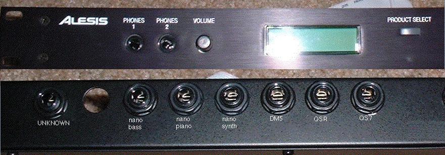
The unit has nine 1/4" jacks on the rear panel (photo here); the middle six are inputs, selected in order as one presses the "Product Select" button on the front panel.
Each jack is a stereo input, normally intended to accept the headphone output of a synth or drum module. I have plugged line-level signals into these jacks; levels are lower, but the unit appears to work with them.
Audio Outputs
On the front panel there are two headphone jacks, which both receive the same stereo signal from the selected source. The front-panel volume control adjusts the level delivered to the phones.
On the rear panel are two 1/4" jacks, separated from the middle six inputs. These jacks appear to be line-level output jacks that provide a copy of the stereo signal going to the phones. One is Left, the other is Right. I haven't yet checked which is which, but logic would dictate that they are in L-R order when viewed from the rear panel.
The level at the line outputs varies with changes in the headphone volume control.
The Other Rear Jack
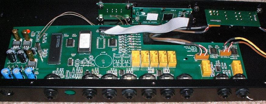
From examination of the PC board, there are pads for two more switching relays and associated components that are unpopulated. It appears that the "solo" rear jack, and the hole next to it where another jack could be installed, are part of this uninstalled circuit.
The selections only rotate through six inputs, not all eight, which implies that on some versions of this unit, the other two jacks are installed and activated in the firmware. It appears that, although the jack is superfluous, the behavior of the unit isn't affected.
Noisy Volume Control
On my unit, I had to spray contact cleaner to get rid of noise in the volume control. It's a cheap unsealed unit, easy to clean.
There appears to be quite a bit of hand assembly, possibly a little rework, as evidenced by a bunch of hand-soldered connections. Possibly these units were machine-assembled en masse in some base configuration, then hand-modified for specific uses.
Possible Uses
I'm just throwing out ideas here, in hopes that I'll find a good one that I can use!
Instrument selector. This is essentially its original purpose. Select among several stereo synths in a studio or live rig. This assumes its performance with line-level signals is good. You could always use the phones output of the instrument, but that may be of lower quality than the instrument's line output. Use it to assign one of several guitars or basses to your amplifier. This assumes instrument-level signals work well, which I haven't tested.
Quickie headphone amp for one or two users. Plug something in the back, select it, and it comes out the front jacks.
Source selector for a small stereo system. Tape, CD, aux, whatever. This is probably superfluous for most stereo amplifiers, which have the same function built-in. And the 1/4" jacks would require adapters.
An effects-unit selector for a studio? Wire one or two aux sends in parallel to multiple FX units (so they all get the same signal at their inputs), and use the Alesis box to choose which FX unit comes back to the aux returns. Sort of a one-sided patchbay. This might actually be useful.
The ROM
The ROM is a 27C512 part; I haven't bothered to check whether this is erasable; it probably is. Someone with an EEProm eraser/burner could read out the entire contents, change the label text displayed in the LCD display, and burn a new ROM. Right now, these text strings are Alesis product names.
For custom applications, it would be great to easily burn a new ROM, but few of us have the proper equipment to do so.
The Next Step
Friend and intrepid experimenter Mike Rivers suggests that it should be possible to wire the input directly to at least one output jack at the phones amplifier. Doing so will bypass the amp for that jack; this will allow audio to pass unmodifed at whatever level it arrives at the input. Because relays are used to perform the switching, the audio should pass through just fine.
This is on my list of things to investigate on a rainy day.
Anyone Have More Info?
Send me email if you have more info. I sent email to Alesis a few years ago on the chance they'd send a schematic. They never replied, and I never followed up.
|